Return-to-home plan blocks
A return-to-home plan is a set of terminal flight paths for a drone in a light show, pre-calculated for many consecutive timestamps of the show. Each return-to-home plan entry allows the drone to safely return to the launch pad from a specific time instant in the show in case of an emergency while avoiding all other drones in the swarm if all of them are switched to a specialized collective return-to-home flight mode.
Each RTH plan entry contains a minimal set of parameters that allow the drone to generate a safe path to the assigned target point and land there, while avoiding all other drones in the swarm that are also performing their own return-to-home maneuvers at the same time. Drones may be assigned to different points in different plan entries, and may also be instructed to simply land in place as a last resort if no safe paths can be generated within the constraints of the RTH plan algorithm.
When the show is switched into collective return-to-home mode, the drone looks up the next available RTH plan based on the current time on the show clock, continues the show until the activation time of that plan arrives, and then switches to the trajectory prescribed by the entry. Each return-to-home trajectory has the same general shape, consisting of the following segments:
-
An optional pre-action delay segment, where the drone hovers in place for a while before starting the main action
-
An optional vertical pre-action "neck" segment, where the drone performs a vertical motion to gain or lose altitude before starting the main action, speeding up from zero velocity to a necessary travel velocity with a constant acceleration, and then slowing down to zero velocity again with the same acceleration at the end of the neck segment.
-
The main action segment, where the drone performs a primarily horizontal motion to fly to the assigned point, or simply hovers in place if the action is to land in place. Note that this segment may also contain a vertical component if the action is to fly to a point with a different altitude, or if the neck segment is not used but a change in altitude is still needed. The velocity profile of this segment starts with a constant acceleration phase from zero velocity to the necessary travel velocity, followed by a constant velocity phase, and ends with a constant deceleration phase to zero velocity again.
-
An optional post-action delay segment, where the drone hovers in place for a while after performing the main action but before triggering landing
-
A final landing segment, where the drone descends to its landing altitude at a predefined average landing speed, and lands there. The descent starts from zero vertical velocity, accelerates with a constant acceleration, then continues with a constant vertical speed, and then decelerates to hit the landing altitude with zero velocity in a way that the prescribed average landing velocity is respected.
The entries of the return-to-home plan simply encode the parameters of the above described generic return-to-home trajectory template so that the specific trajectory can be generated by the drone at runtime based on the parameters of the entry and the current state of the drone at the time of switching to collective return-to-home mode.
Since many entries may refer to the same point (or points with identical horizontal positions but different altitudes) in the RTH plan, the X and Y coordinates of these points are encoded separately in an array and are referred to later from the entries by numeric indices to save some space.
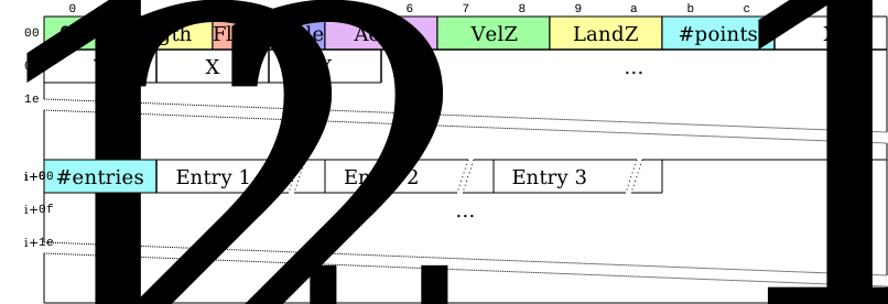
The basic byte-level structure of a return-to-home plan block is as follows:
Scale factor

The 7 low bits of the scale factor byte contain an unsigned integer that acts as a multiplier for the coordinates in this block; each coordinate - both absolute and relative - should be interpreted as this many millimeters. For instance, setting the scale factor to 10 means that all coordinates in the block are encoded in centimeters. The individual coordinates will be encoded with 16-bit signed integers in the block, so you should use the smallest possible scale factor that still allows you to express all the coordinates in the block in a 16-bit signed integer.
The 8th bit of the scale factor byte is reserved.
Acceleration (Accel)
The acceleration value used during all linear segments of all RTH plan entries is encoded as a 16-bit unsigned value, in millimeters per second squared [mm/s/s]. The acceleration value is not scaled with the scale factor.
Landing speed (VelZ)
The average vertical landing speed used at the end of all RTH plans, encoded as a 16-bit unsigned value, in millimeters per second [mm/s]. The landing speed value is not scaled with the scale factor.
Default landing altitude (LandZ)
The default landing altitude used at the end of all RTH plans, encoded as a 16-bit signed and scaled value.
Point array
The points in the RTH plan are encoded by storing the length of the array first in a two-byte unsigned integer, followed by the points themselves. Each point is a pair of X and Y coordinates, encoded as two-byte signed integers. Optional arrival altitudes to the final RTH position and final landing altitudes are encoded as action parameters for a given plan entry (see Entry body).
| Do not forget to multiply the encoded coordinates with the scale factor to obtain physical coordinates in millimeters. |
Plan entries
The entries of the RTH plan are encoded by storing the number of entries first in a two-byte unsigned integer, followed by the entries themselves.
Each entry has the following byte-level layout:

Flags byte
The flags byte has the following structure:

From right to left (LSB to MSB), the bits of the flags byte are as follows:
- Neck
-
The Neck bit is set to 1 if the entry has a vertical pre-action neck segment.
- TargetXY
-
The TargetXY bit is set to 1 if the entry has a main action segment with a non-empty horizontal component.
- TargetZ
-
The TargetZ bit is set to 1 if the entry has a main action segment with a non-empty vertical component.
- LandZ
-
The LandZ bit is set to 1 if the entry has a non-default landing altitude. 0 means that the default landing altitude of the RTH plan is used.
- PreDly
-
The PreDly bit is set to 1 if the entry has a non-zero pre-action delay.
- PostDly
-
The PostDly bit is set to 1 if the entry has a non-zero post-action delay.
The reserved bits must be set to zeros. This allows us to assign meaning to these bits in the future as long as zero preserves the current behaviour. Parsers must ignore the reserved bits.
The overall Flags value of 0 has a special meaning. If all the flag bits are zero, the entry is assumed to have exactly the same body as the previous entry, but its body parameters will not be encoded to save space and bandwidth. If the very first entry of the plan has a Flags value of 0 (i.e. there is no previous entry to copy), the entry is a "land in place" entry with all body parameters at their default values.
Entry duration
Entry duration is the time interval since the activation time of the last RTH plan until the activation time of the current entry, encoded as a varuint, in seconds. (RTH plans with a granularity smaller than a second are not supported). The first entry duration is assumed to encode the number of seconds since the start of the show clock. The activation timestamps of the entries are not encoded directly. They can be calculated by summing the durations of all the preceding (and current) time intervals.
| It is important to emphasize that this field is the duration of the time interval between entry activation timestamps, and not the duration of the return-to-home trajectory prescribed by the entry. The latter can be inferred from the parameters of the entry, but is not encoded explicitly in the file. |
Entry body
The content of the entry body depends on the state of the Flags byte, and may contain the following parts in order:

- Neck length
-
When the Neck flag bit is set, the Neck length part contains the length of the vertical pre-action neck segment as a relative coordinate (16-bit signed integer, scaled). Note that in a typical RTH plan the neck is usually traversed downwards, hence the length will be negative (since the Z axis points upwards). The field is omitted when the Neck flag bit is not set.
- Neck duration
-
When the Neck flag bit is set, the Neck duration part contains the duration of the traversal of the vertical pre-action neck segment, as a varuint, in seconds. The field is omitted when the Neck flag bit is not set.
- Target index
-
When the TargetXY flag bit is set, the Target index part contains the index of the point that the main action segment of this entry refers to, as a varuint. The field is omitted when the TargetXY flag bit is not set.
- Target Z
-
When the TargetZ flag bit is set, the Target Z part contains the arrival altitude corresponding to the point that the main action segment of this entry refers to, in standard coordinate format (16-bit signed integer, scaled). The field is omitted when the TargetZ flag bit is not set.
- Duration
-
When the TargetXY or TargetZ flag bit is set, the Duration part contains the duration of the main action segment of this entry, as a varuint, in seconds. The field is omitted when both the TargetXY and TargetZ flag bits are not set.
- Landing Z
-
When the LandZ flag bit is set, the Landing Z part contains an entry-specific non-default landing altitude (16-bit signed integer, scaled). The field is omitted when the LandZ flag bit is not set, and in this case the default landing altitude of the RTH plan is used.
- Pre-delay
-
When the PreDly flag bit is set, the Pre-delay part contains the duration of the pre-action delay as a varuint, in seconds. The field is omitted when the PreDly flag bit is not set.
- Post-delay
-
When the PostDly flag bit is set, the Post-delay part contains the duration of the post-action delay as a varuint, in seconds. The field is omitted when the PostDly flag bit is not set.
If the Flags byte byte is zero, the entry must be assumed to have exactly the same body parameters as the previous entry (even though none of them will get encoded). If you ever need to encode a valid entry with all entry body flags at zero, simply add e.g. a pre-delay of 0 and set its flag bit to 1 to differentiate it from the special meaning of all flags at zero.