Trajectory blocks
Trajectory blocks encode the trajectory of the drone to follow during a light show using a sequence of segments, where each segment may be:
-
a hover event
-
a straight-line transition
-
a cubic Bézier curve
-
or a higher-order Bézier curve of degree 7.
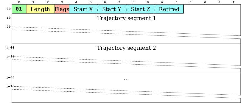
The trajectory is assumed to be continuous, i.e. the last point of each trajectory segment is the same as the first point of the next segment. The basic byte-level structure of a trajectory block is as follows:
Flags byte
The flags byte has the following structure:

The MSB of the flags byte must be set to zero by writers. This bit was used by earlier versions of the format to mark the presence of an embedded yaw track, so it is permanently retired: parsers must ignore it, and it will never be assigned a new meaning (see also Legacy embedded yaw track). The remaining bits contain an unsigned integer that acts as a scale factor for the coordinates in this trajectory block; each coordinate should be interpreted as this many millimeters. A scale factor of zero means that the trajectory is empty. For instance, setting the scale factor to 10 means that all coordinates in the trajectory block are encoded in centimeters. The individual coordinates will be encoded with 16-bit signed integers in the block, so you should use the smallest possible scale factor that still allows you to express all the coordinates in the trajectory in a 16-bit signed integer.
Start coordinates
The start coordinate of the trajectory is encoded as a sequence of three 16-bit signed integers corresponding to the X, Y and Z coordinates of the drone. An additional, fourth 16-bit signed integer is also added for backward compatibility reasons. Writers must set it to zero. This field was used by earlier versions of the format to store the start yaw of an embedded yaw track, so it is permanently retired: parsers must ignore its value, and it will never be assigned a new meaning (see also Legacy embedded yaw track).
Trajectory segments
Trajectory segments consist of a three-byte header followed by a list of control points:

The encoding field specifies how the X, Y and Z coordinates will be encoded in the segment. For each of the X, Y and Z coordinates, there are two bits in the encoding field:
-
00means that the coordinate is constant throughout the section (i.e. it is a zero-order Bézier curve). -
01means that the coordinate changes linearly (it is a Bézier curve of order 1). -
10means that the coordinate changes according to a cubic Bézier curve. -
11means that the coordinate changes according to a full 7th degree polynomial, expressed again as a 7th degree Bézier curve.
The order within the encoding field is as follows:

The two most significant bits must be set to zeros by writers. These bits were used by earlier versions of the format to encode a yaw axis; parsers must still be prepared to handle them as described in Legacy embedded yaw track.
The next two bytes are the duration of the segment as an unsigned 16-bit integer, in milliseconds. This means that the longest segment allowed is about 65 seconds long. If you have longer segments, you need to slice them to smaller segments until you fit within the two-byte limit. A duration of zero is allowed and represents an instantaneous jump from the start point to the end point of the segment; when the trajectory is evaluated at a time instant that falls within such a segment, the position is the midpoint of the jump.
For instance, a header containing 0x0a 0xd0 0x07 means that the segment is 2000 milliseconds long (because 0x07d0 = 2000), and it will have a constant Z coordinate. Cubic Bézier curves will be used to describe the X and Y coordinates of the segment. (This is because 0x0a = 00 00 10 10 in binary).
Then, for each dimension (X, Y and Z) there are as many coordinates (encoded as 16-bit signed integers) as the order of the corresponding Bézier curve according to the corresponding bits in the encoding header (zero for 00, 1 for 01, 3 for 10 and 7 for 11).
Each coordinate belongs to an interim control point of the Bézier curve, except the last one, which belongs to the end point of the Bézier curve.
Start points are not encoded because they are the same as the end point of the previous segment.
Obviously, when the header specifies that a coordinate is constant, it means that we do not need to store the control points for that coordinate at all (there would be only a single control point, but we already know that it is the same as the last control point of the previous segment). For linear segments, we only need to store the end of the segment. For cubic Bézier segments, we need to store the first and second control point and the end of the segment. This can result in significant space savings if the trajectory consists mostly of linear segments and cubic Bézier curves, if the movement mostly occurs in the X-Y, X-Z or Y-Z plane. Note that cubic Bézier curves are enough to ensure C0, C1 and C2 continuity (in position, velocity and acceleration) for the trajectories.
| Do not forget to multiply the encoded coordinates with the scale factor to obtain physical coordinates in millimeters. |
Legacy embedded yaw track
Earlier versions of the format could embed a yaw track in the trajectory block itself. The canonical way of encoding the yaw of the drone is now the Yaw control blocks, and writers must not produce the legacy embedded yaw track any more. However, parsers may still encounter files containing it, where:
-
the MSB of the flags byte is set to 1 to mark that the trajectory contains yaw information,
-
the fourth field of the start coordinates contains the start yaw of the drone in 1/10th of a degree,
-
bits 7-6 of the encoding byte of each segment specify the encoding of a fourth, yaw axis, with the same meaning as the two-bit formats of the X, Y and Z axes (
00,01,10and11). In this case, the corresponding number of additional 16-bit signed integers (zero for00, 1 for01, 3 for10and 7 for11) follow the control points of the Z axis in the segment.
Parsers must ignore the yaw values themselves, but they must still skip the additional bytes declared by bits 7-6 of the encoding byte so that the subsequent segments are parsed correctly.
| As a consequence, the MSB of the flags byte, the fourth field of the start coordinates and bits 7-6 of the encoding byte of a trajectory segment can never be reassigned to a different meaning in later versions of the format. The MSB of the flags byte and the fourth field of the start coordinates are permanently retired, and bits 7-6 of the encoding byte will always declare the number of additional 16-bit values to skip after the control points of the Z axis. |